The fundamental process of forging involves applying compressive forces to the workpiece using a variety of dies and tools. Hammering metal ...

The fundamental process of forging involves applying compressive forces to the workpiece using a variety of dies and tools


The fundamental process of forging involves applying compressive forces to the workpiece using a variety of dies and tools. Hammering metal with stone tools is one of the most ancient and significant metalworking processes used to create jewellery, coinage, and other items. Large turbine rotors, gears, bolts and rivets, cutlery, hand tools, countless structural pieces for machinery, aeroplanes, and trains, as well as an assortment of other transportation equipment are examples of forged parts nowadays.


Blacksmiths have historically used a strong hammer and an anvil to accomplish simple forging operations. But most forgings need tools like a press or a powered forging hammer, along with a set of dies.


Depending on the homologous temperature, forging can be done at room temperature (cold forging) or at higher temperatures (warm or hot forging). Because the workpiece material is stronger, cold forging requires higher forces, and the material must be sufficiently ductile at room temperature to allow for the required deformation without cracking. Cold-forged parts have accurate dimensions and a fine surface quality. Although hot forging uses less force than cold forging, the components' surface finish and dimensional accuracy suffer as a result. Additional finishing processes, like heat treatment to change characteristics and machining to get precise final dimensions and a smooth surface, are typically applied to forgings. Precision forging, a key example of net-shape or near-net-shape, can reduce these finishing processes. When a material is forged, it is distorted by an impact load or a steady load. Forging is categorized as press forging or hammer forging depending on the kind of loading. Press forging includes progressive stresses, whereas hammer forging involves impact loads.


Open Die Forging

The workpiece is compressed in this method between two platens. Material flow in a lateral direction is unrestricted. Open die forging is a method that uses relatively simple-shaped dies to create products by gradually deforming them. The bottom die is fastened to the press bed or hammer anvil, and the top die is fastened to the ram. Heat is applied to the metal workpiece above recrystalline temperature, between 1900 and 24000 Celsius. The majority of open-die forging is done using flat dies.
pen die forging is a method that uses relatively simple-shaped dies to create products by gradually deforming them
Cogging, fullering, and edging are the three primary categories of open die forging. Cogging: Cogging, also known as drawing out, is a process wherein narrow dies are used to reduce an ingot's thickness to billets or blooms. Convex or concave-shaped dies are used in fullering and edging operations to lower the cross-section. As a result of material distribution, thickness decreases and material elongates. Upsetting is an open-die forging process.

Advantages of Die forging

Disadvantages of Die forging

Products are with greater strength

Less accuracy and tolerances

Fatigue resistance of the parts improved

Reduce voids

Need to machine parts to get the desired accuracy and features.

Capable of producing very large parts which weigh about 136 metric tonnes.

Applications of Open die forging

Less material wastage


Products have fine grain size and continuous grain flow


Closed Die Forging

While impression die forging and closed die forging are very similar processes, closed die forging requires extremely precise control over the initial material removal to prevent flash formation. Otherwise, impression die forging is akin to the procedure. This method works well for large-scale production.
closed die forging requires extremely precise control over the initial material removal to prevent flash formation

Advantages of Closed forging

Disadvantages of Closed forging

Reduce or no machining

No economic to small or short production runs due to the high cost of die

Less or no machining is required for its close tolerances

High setup cost for furnace dies and machines

Dimension with tight tolerances part can be made

Closed die forming is a dangerous process

Better surface finish and mechanical properties


Cost-effective for large production runs


Application of closed die forging

Railway, petrochemical, electrical, lifting and safety systems, industrial and agricultural machinery sectors.

Mining drilling bits, forestry wear parts

Impression Die Forging


The workpiece is pressed between the dies in impression die forging. The necessary shape is formed between the closing dies as the metal spreads to fill the cavities sunk in the dies. "Flash" is the term for a material that is forced out of the dies. As the top hits the anvil, the flash gives the dies some cushioning. The flash surrounding the workpiece is chopped off and thrown away as scrap. A good forging requires the material to fill the dies all the way to the top. It might take multiple hammerblows to accomplish this; one blow might not be enough.

Drop Forging

A closed impression die is used in drop forging to give the component the correct shape. The material inside the die cavity is repeatedly hammered to shape it. Drop hammers are the names of the tools used to deliver the blows.

A drop forging die is made up of two parts. The die's upper half is fixed to the ram, and the lower half is fixed to the machine's anvil. The lower die holds the heated stock. The metal is struck by the ram four or five times in rapid succession, causing the metal to spread out and fill the die cavity completely. The entire cavity is created when the two die halves close.

PRESS FORGING

Press forging dies and drop forging dies are comparable in terms of operation. Unlike drop forging, which shapes the metal through a succession of blows, press forging shapes it through a single, continuous squeezing action. It is achieved by using hydraulic presses to produce this squeezing. As a result of the hydraulic presses operating continuously, the material deforms uniformly throughout the depth. In drop forging, more hammer force is probably going to be transferred to the machine frame, whereas in press forging, the stock absorbs all of the force. Press forging yields a clean impression as opposed to jarred impressions, which are similar to drop-forged components.

Press forging has a smaller draft angle than drop forging. However, deforming requires a larger press capacity, so only smaller components are press forged in closed impression dies. 

The two halves of the die post are fastened to the bottom die to provide the required alignment. This allows the top die to slide only on the post and register the proper alignment. Better tolerance is ensured for press-forged components as a result.

Forming is the one of manufacturing methods which is used to make some objectives. Metal forming is the metalworking process that is used to...


Forming is the one of manufacturing methods which is used to make some objectives

Forming is the one of manufacturing methods which is used to make some objectives. Metal forming is the metalworking process that is used to form metal parts for different shapes through deformation. The material piece is reshaped without adding or removing material.


Hot Forming

The hot hot-forming process is used very frequently to cast industrial products and parts. The raw materials are available form of sheets, tubes, bars or wire.

The hot hot-forming process is used very frequently to cast industrial products and parts. The raw materials are available form of sheets, tubes, bars or wire. In this process, heat is applied to the material to soften. Then, some of the required pressure is applied to get the desired shape of the metal. This process is also capable of forming a variety of complex parts and holds relatively tight tolerances.


Most hot-forming processes are complex due to the involvement of adiabatic heating, die chill and microstructural changes.


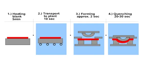
Hot hot-forming process is one of sheet forming processes of sheet metal. This process is also known as hot stamping or press hardening. All forming processes are run above the recrystallization temperature of the material. The material recovers and softness during the hot forming process of sheet metal. The hot sheet metal is brought into contact with the hot die and a hot punch is pressed into the die to form the shape and then apply forming pressure for a period.


A direct (one-stage) hot-forming process is commonly used due to forming and part hardening being done in one operation.


Advantages of hot forming

Disadvantages of hot forming

Accurate forming

Burr formation

Complex shapes

Furnaces cause high energy cost

Consistent thickness

The surface finish is poor

Higher surface profile tolerances

The component can wrapped in the worst-case

Resistance to cracking

The surface of the component slightly scaled due to the high working temperature

Good strength


Lower cost


Low spring back


The uses of the hot-forming process are as below, 

In the automobile industry: -


Side members, door reinforcements, sills, roof frames, roof rails, and bumper supports.


Cold Forming

The cold forming process is the metal forging process at bear room temperature or slightly above room temperature.


The cold forming process is the metal forging process at bear room temperature or slightly above room temperature. Forming metal at cooler temperatures may retain or enhance the tensile strength of the material. This process is a high-speed process that allows the manufacture of large amounts of metal-based products in a fast, consistent and cost-effective way.  Cold-formed parts have greater yield, higher tensile strength and superior surface finish when compared to hot-formed parts.


The cold-forming process can be classified into four major groups, such as squeezing, bending, drawing, and shearing. However, higher loads are required to do the cold forming process and deformation is low compared hot forming process. Also, a high degree of manufacturing experience is required to achieve complex geometry parts.


Advantages of Cold-forming

Disadvantages of Cold forming

No heat is required, so low energy is required

Harder tools and dies are needed due to metal is harder

Better surface finish

Low deformation

Superior dimensional accuracy

Material with low ductility cannot be sold formed.

Improve strength properties

Metal surfaces must be clean and scale-free

Contamination problems are minimized

Residual stress may occur

Material savings & elimination of scrap

Higher forces required for deformation

Inexpensive


Big production rate and long life


Material savings & elimination of scrap


Application of the cold forming process,

Fasteners, screws, nuts, bolts, electrical contacts, and rivets


Warm Forming


Warm forming is the metal deform process in which metal is heated to a temperature that maximizes the material's malleability without allowing re-crystallization, grain growth, or metallurgical fracture.


Warm forming is the metal deform process in which metal is heated to a temperature that maximizes the material's malleability without allowing re-crystallization, grain growth, or metallurgical fracture. Warm forming aims to combine the strong points of hot and cold forming. Better surface finishes can be achieved than hot forming. Temperature control is difficult in this process. If more complex parts are formed, precision is low. The warm-forming process is suitable for medium-scale productions.


Advantages of Warm forming

Disadvantages of Warm forming

Reduce tooling loads compared to cold-forming

Lower precision than cold forming


Increased steel ductility

Strict temperature control

Lesser amount of heat energy requirement than hot forming

Greater press loads than hot forming

Lesser thermal shock on tooling than hot forming

Required skilled engineering to design appropriate tooling

Better dimensional control than hot forming


Better precision components than hot forming


In the automotive industry, warm-formed parts are used (Door panels, fenders). In such applications, warm forming of certain aluminium alloys may be cost-effective because of reduced vehicle weight and fuel consumption.

Computer-aided design is denoted as CAD and Computer-Aided Manufacturing is denoted as CAM and those two are related to two different classe...

History of CAD/CAM, Computer Aided Design and Computer Aided Manufacturing

Computer-aided design is denoted as CAD and Computer-Aided Manufacturing is denoted as CAM and those two are related to two different classes of application programs which support the design, build and analysis of simple or complex product assemblies, and plants. 20 years ago, these two programs were introduced to the market. At that time, those programs were expensive and difficult to learn. As an example, the McDonald-Douglas CAD program which was used to design aircraft by Boeing was more expensive at half a million dollars a highly powerful workstation computer was needed and lots of time had to be spent to learn it. However, with recent advanced technologies and superpowers, fast personal computers, high-quality friendly GUI interfaces, and sufficiently developed calculation algorithms, CAD/CAM can be used in-house manner for engineering and manufacturing applications. Therefore, engineers can design without support from the drafter.

Computer Aided Manufacturing (CAM) is based on computer numerical Control (CNC) with computer software tools which are pre-programmed to aid in moving factory tools and machinery. G-code can be identified as the most widely used CNC programming language. Computer Aided Design (CAD) is used to generate electronic files to print, for manufacturing purposes and machining operations. The productivity of the designers, and engineers and the quality of the designs can be enhanced using CAD software. CAD software is a valuable technical platform for both engineers and designers who are working in a range of industries such as automotive, aircraft, agriculture, etc. although, CAD and CAM are two specific areas, both software tend to be used together as CAD/CAM.

CAD originated in three separate sources which are to automate the drafting process, the testing of designs by simulation, and to facilitate the flow from the design process to the manufacturing process using numerical control (NC) technologies. The biggest advantage was that time-saving in computer modelling over conventional drafting methods and, models can be changed or updated by changing the parameters of the model. Computer modelling software was used in high-tech industries such as aerospace, military and semiconductors in the early times. After that, computer numerical control technologies were widely used in many applications in of 1960s and this was the initial source for linkage between CAD and CAM. CAD/CAM integration between design and manufacturing stages which CAD/CAM-based production process.


Usage of CAD/CAM rapidly increased after the early 1970s for making silicon chips and microprocessors on a large scale to design affordable computers. Therefore, the price of the computers continuously declined and performance has improved. Also, large-scale firms frequently used CAD/CAM for large-scale mass production techniques. Some manufacturing processes were controlled using several computers but were not strictly called CAM due to geometric parameters that have not been taken as control data.

The history of CAD


Computer-aided design software is used by engineers, and designers in various industries to design various products such as bridges, roads, aircraft, cloths, mobile phones, ships, TVs, etc. CAD software history began with “The Elements” which Euclidian geometry was written by mathematician Euclid Alexandria, in 350 B.C.


The initial term “computer-aided design” was introduced by Douglas T. Ross in the early 1950s when he was working as a researcher at the Massachusetts Institute of Technology (MIT) to develop military radar technology and computer display systems. Before exploring CAD, Automatically Programmed Tools (APT) which is used to create Automated Engineering Design (AED) has been developed by Ross. After that, a discussion was started with MIT to expand technologies with earlier experiences.


The initial user of the CAD was Patrick Hanratty at the General Motors Research Laboratories. The Design Automated by Computer (DAC) was developed as the first CAD system with interactive graphics. The first commercial CAD/CAM code was developed by integrating numerical control programming software named PRONTO in 1957. Therefore, Patrick Hanratty was called as the father of CAD/CAM. The first true CAD software was the Sketchpad which was developed by Ivan Sutherland in the early 1960s as a result of his Ph.D. thesis at MIT.

The history of CAM

Computer-aided manufacturing (CAM) technology has been referred to with numerical control (NC) software which is used to create G-code. G-codes are used to operate the computer numerical control (CNC) machine tools to manufacture parts and products. Computer-generated design or CAD drawing is used to take information to create instructions to control the movements of an automated tool. Computer-aided manufacturing software enhances the production and manufacturing process.


Computer-aided manufacturing processes began to develop in the 1950s and also were used in the 1970s. Using CAM software, designs can be directly imported into CAM to produce them while providing only raw materials and instructions such as feed rate, speed and dimension. NC machines were used for CAM technology in the early 1950s and highly developed CNC machines are available recently.

Computer aided manufacturing (CAM) technology has been referred with numerical control (NC) software which is used to create G-code.

The first NC machine was developed by John T Parsons in 1949. The idea to develop a punch card machine was initiated while trying to find ways to build helicopter rotors to speed up the manufacturing process. However, the developed one was not properly working and tried to develop further under US Air Force funds. Further, the first NC prototype was developed with the aid of the Servomechanism Laboratory at MIT.

CAD/CAM History in the apparel industry

The first label-sewn creation machine for garments was designed by Charles Frederick in 1858, the 19th century with the modern fashion industry beginning. Initially, labels were drawn using pencil and paper. When changing society and culture, demand for labels and label variations increased and the process was challenged. The reason behind this was that styles and customer tastes were frequently changed in the market. Therefore, alternative solutions were tried to aid in enhancing the design and manufacturing process.

CAD was applied when doing designs using computers by incorporating it into the apparel industry. Currently, CAD programs are frequently used and essential for fashion designers and garment factories. The function of CAD in the apparel industry is pattern making, making markers, grading patterns virtual test fitting etc. CAD tools also enhance productivity and reduce design time.

CAD programs are frequently used and essential for fashion designers, garment factories.

Advantages

Designs can be changed without erasing and redrawing


Due to the “zoom” feature of CAD, the model can be magnified and inspected as necessary by to designer


Due to the three-dimensional modelling feature, the model can be rotated on any axis


Machine capabilities can be improved


Material wastage can be reduced using CAD/CAM


Client Accessibility is improved


Save time


Easy to share and less design effect


High-quality and reliable finish products can be manufactured using CAM, due to fewer human errors


Disadvantages

Due to computer-related tasks, data may be lost due to sudden failure of the devices


Initial establishment cost is high

Due to the use less workers, traditional skills will be lost due to increasing unemployment

Maintenance and update cost is high


Conventional or Traditional Design Conventional design is done according to the known set of parameters, which someone has done, found, inve...

Conventional design is done according to the known set of parameters

Conventional or Traditional Design

Conventional design is done according to the known set of parameters, which someone has done, found, invented or innovated. These cases are well-known principles that are established and these can be used to do similar designs while only changing the capacities, power, strength, size, and other mechanical and performance parameters.


For example as below,


Gearbox design

Die design

Mould design


Also, the standard machine element designs can be considered traditional designs. These are already design concepts and we can use them to design new ones by changing the design parameters.


For example as below,


Gears

Belts

Pulleys

Shafts

Springs

There are a lot of handbooks in mechanical engineering to do traditional design and we can follow these guidelines and catalogs. Also, there are lots of software to inbuilt traditional elements.


Innovative design

The novelty is the important thing to stay in the competitive market to fulfil user demand. These upgrading changes can be identified as design by evaluation. Innovative design is a process of identifying potential requirements and developing or modifying the product or ideas by using creativity and new technologies. Novelties are in slowly moving paths. A novel concept or product is innovated with a sound research approach and this innovated item will be improved gradually by scientific validation and research. These findings are used to further research whether they are valuable or not. Physically realizable, economically worthwhile, and financially feasible are the important characteristics of remarkable inventions which are created by inventors.


A few examples are,


Acoustic Wave Separation

Solar power-generating windows which are fully transparent

An absorber design using natural hyperbolic material for harvesting solar energy.

Hybrid simulation of thunderstorm outflows


Adaptive Innovation

Adaptive innovation is one of the common methods that can be used to develop an innovative concept or product nowadays. Several development inventions in other technologies or application fields are combined to develop a combined concept or product with lots of advantages. Adaptive innovation is considered as ideas, testing, thinking, and pushing again and again. The different fields or applications are subjected to development using adaptive innovation. These adoptions result in replacing the existing traditional method and making some tasks easy. As an example, image processing technology initially was introduced for satellite imagery, however, it has adapted to many different fields nowadays face detection (security systems), quality control methods, medical imaging, etc.


Adaptive innovation mainly helps with problem-solving and the creativity model aims to increase collaboration and reduce conflict. In adaptive innovation, six areas of never-ending, persistent work for Adaptive Innovation emerge,


Trends & Needs
Discoveries
Insight
Innovation
Invention
Products & Services

Inventive Innovation

This is an engineering term related to the invention. Inventive innovation can be identified as a major step forward on the technology front or it can be a novel product a completely new one or an earlier non-existent product. Also, concepts or methodology can be identified as inventive innovations. Device or originate which is known as to invent in a novelty of a new kind or nature hitherto unknown. Thus, inventive innovation is incorporating a change hitherto unknown.


Frist electrical Build

Frist generator

First Motor

First Steam engine

Wheel

Laser

Semiconductor Chip

SolidWorks simulation is a design analysis tool based on a numerical technique called Finite Element Analysis (FEA). This is used to solve p...

This image shows a FEA model. Use SolidWorks simulation to find a maximum stress on this pin body

SolidWorks simulation is a design analysis tool based on a numerical technique called Finite Element Analysis (FEA). This is used to solve problems described by a set of partial differential equations. These kinds of problems can be found in various engineering disciplines, such as machine design, fluid dynamics, and others.


In mechanical engineering, FEA is widely used to solve problems related to structural, vibration, and thermal problems. There are other numerical solution analysis tools, such as the Finite Difference method, Boundary Element Method or Finite Volumes Method. However, FEA became a common tool due to its versatility and high efficiency. The FEA method can be used to solve problems ranging from very simple to very complex. Mechanical design engineers use often it in the design stage. The basic phases in each FEA project are always the same, regardless of the project's complexity or area of application. The geometric model is the starting point for any analysis. In SolidWorks, a SolidWorks part or assembly is a geometric model containing applicable material properties, loads, and restrictions.


The model is discretized (meshed) for the analysis. The geometry is divided into relatively small and simple-shaped entities known as finite elements throughout this procedure. The elements are referred to be finite to indicate that they are not infinitesimally small, but rather reasonably small in respect to the overall model size.


Each FEA application requires three steps,


Preprocessing:

The type of analysis, material properties, loads and restraints are defined and the model is split into finite elements.


Solution:

Computing the desired results.


Postprocessing:

Analysis of the results.


There are four main steps in the FEA methodology,


Building the mathematical mode:

The geometric shape is represented by a SolidWorks part or assembly. Then model is meshed into correct and reasonably small, finite elements. This meshing process is very important because good mesh geometry provides the correct solution for the data of interest, such as stress, displacements, and etc.

Defeaturing:

This is called simply the geometric model by removing or suppressing features which are insignificant to analysis. As an example, removing thread features, and logos.

Idealization:

The process of reducing a real structure to a collection of finite elements. At its most basic, the operation would consist of a single CAD-generated geometric model that is fully meshed in a single operation.

Clean-up:

This is required but not always. This process is used to maintain the higher quality requirements. CAS quality-control tools can be used to check for any problems. Such as multiple entities or sliver daces.

This image shows a pre processing of FEA. How to create a geometric model by defeaturing to improve the simulation speed.

Build a Finite Element Model

The geometric model is split into finite elements through a process of discretization, better known as meshing. Discretization visually manifests itself as the meshing of geometry. However, loads and supports are also discretized and, after the model has been meshed., the discretized model loads and supports are applied to nodes of the finite element mesh.

This image shows the full description of the FEA from the pre-processing to post-processing. In this image, there is meshing process

Solve the Finite element Model

After completing the finite element model, a solver in Solidworks simulation is used to get the desired results.

Analysis Results

This is the most difficult step in FEA. There are a lot of details in the results in many formats.

Stress
Strain
Displacement
Factor of Safety
Natural Frequency
Temperature

Errors in FEA

The process of the FEA introduces unavoidable errors while creating mathematical models and discretizing. such as modelling errors (idealization errors) in the formulation of mathematical models discretization errors in the meshing process and numerical errors in solutions.


Only discretization error applies to FEA. Therefore, discretization errors can be controlled using FEA methods. modelling errors can be controlled by correcting the model before the FEA. Solution errors are difficult to control because they come from the solver.