Sand mould casting is widely used in industry to make from small items to large items and from very simple items to complex items. Sand cast...

This is the basic image of the sand mold casting. This image shows how to apply molten metal into mold.

Sand mould casting is widely used in industry to make from small items to large items and from very simple items to complex items. Sand casting is used for both ferrous and non-ferrous materials. Sand is used to make molds and a small amount of clay and water is added to improve bonding grains and cohesion and mold-ability.  Mold is usually made in two pieces.

This image shows the cross section of the sand mold casting. Parts of the sand mold can be clearly seen.

Figure 1: Sand Mold Casting

Pattern

The required shape on the top and bottom halves of a sand casting mould is prepared by patterns. Patterns approximately duplicate the casting shape. A pattern provides the required shape of the product and sand is packed around the pattern. When removing the pattern, the mould cavity can be shown to pour liquid materials.

Core

The core is used to place into a mould cavity to form the interior surface or features of the castings.

Flask

This is used as a frame to hold the moulding material. This is a rigid wood or metal frame.

Cope

This is the top half of the mould or core of a two-part mould, flask and pattern.

Drag

This is the bottom half of the mould or core of a two-part mould, flask and pattern.

Mold Cavity

This is the cavity of the desired shape to be cast.

Riser

The riser is also used as a reservoir of liquid material. Liquid material in the riser flows into the mould cavity to compensate for any shrinkages.

Gating system

A gating system is used to deliver the molten material to the cavity. A gating system is a network of connected channels.

Vent

This is an additional channel to remove gasses which are in the cavity or generated during the pour.

Parting line

The parting line is the interface between the cope and drags halves of the mould, core or pattern.

Sprue

The vertical portion of the gating system.

Choke

This is the cavity which is located at the base of the sprue. This allows to flow of liquid material smoothly into the casting cavity.

Runners

Horizontal channels are called runners.

Pouring Basin

The top of the sprue is made large. This is called pouring basing to ease the pouring of liquid material without spilling.

After solidifying the liquid material, if the mould is broken remove the cast item. Therefore, a new mould is needed for each casting. Therefore, sand casting is an Expendable casting process.


Microelectromechanical system (MEMS) MEMS (Microelectromechanical system) is used to integrate with devices and systems that combine mecha...

Microelectromechanical system (MEMS)

MEMS (Microelectromechanical system) is used to integrate with devices and systems that combine mechanical and electrical items. Integrated circuit (IC) batch processing techniques are used to fabricate the MEMS systems and they range from micrometres to millimetres. MEMS systems can control and actuate on the micro-scale and generate effects on the macro scale.


MEMS is called Microsystems Technology (MST) in Europe and Micromachines in Japan. MEMS are fabricated through a micromachining process while silicon and other substrates are manipulated sophisticatedly. Bulk and surface micromachining and high aspect ratio micromachining (HARM) processes are used to remove parts of the silicon or add additional structural layers to form the mechanical and electromechanical components. Therefore, MEMS shows either the mechanical properties of silicon or both electrical and mechanical properties.

This image shows the schematic illustration of the MEMS and NEMS. What are the main components related to MEMS

Figure 1: Schematic illustration of MEMS

Generally, microsensors, microstructures, microelectronics, and microactuators are integrated into one silicon chip.


Microsensors: - Detect the changes in the system’s environment, such as thermal, mechanical, magnetic, chemical, and electromagnetic information.


Microelectronics: - The detected changes are processed by microelectronics and give the signal to microactuators to react and create a re-change to the environment.


MEMS components are usually very small and microscopic. But MEMS is not just about the mechanical components miniaturization process. Although, MEMS can be identified as a manufacturing process which is used to design and create complex mechanical devices and systems and their electronics. The batch fabrication technique is used for the MEMS manufacturing process. As an example, gears, levers, motors and steam engines are manufactured.


The size of MEMS components is between 1-100 µm and MEMS sensors are generally classified as the range in size 20 µm-1 to mm.


Nanoelectromechanical systems (NEMS)

Nanoelectromechanical systems are denoted as NEMS. This is the technology that can be used to integrate electrical and mechanical functions in Nanoscale. NEMS are the next logical miniaturization step from the microelectromechanical system (MEMS). NEMS are fabricated using a micromachining process. NEMS are very small and hundreds of NEMS devices can be installed in one space of microdevice that performs the same functions.


NEMS is also integrated with sensors, electronics, actuators, photonics, energy, fluidic, chemistry and biological systems that are enabled by sub-micrometre and engineering precision.


NEMS technology is currently used in low and medium-volume applications.

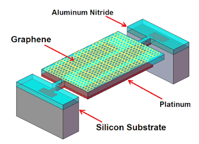
This image shows a Aluminium Nitirde Piezoelectric NEMS devices using 2-dimensionsl Electrode Material.

Figure 2: Aluminum Nitride Piezoelectric NEMS devices using 2-dimensional Electrode Material


The airflow over the wing increases its speed causing a reduction in pressure; this generates a force ( lift ) perpendicular to the chord of...

The airflow over the wing increases its speed causing a reduction in pressure; this generates a force (lift) perpendicular to the chord of the aerofoil. The airflow below the wing moves much more slowly generating greater pressure and less or negative lift. See the article Bernoulli's Principle for further information.

The distance between a wing root and wing tip is the length of the wing. Wingspan is the distance from one wing tip to the other wing tip. The ratio of wing length to chord is called the aspect ratio. The amount of lift and drag generated by an aerofoil depends on its shape (camber), surface area, angle of attack, air density and speed through the air.

The objective of aerofoil design is to achieve the best compromise between lift and drag for the flight envelope in which it is intended to operate. Aerofoil surfaces include wings, tail-planes, fins, wingletspropeller blades and helicopter rotor blades. Control surfaces (e.g. ailerons, elevators and rudders) are shaped to contribute to the overall aerofoil section of the wing or empennage.


This image shows the schematic illustration of air flow over the wing of the aircraft. There are main components, such as angle of attack, downward force.
Schematic diagram of Air Flowing